
An automatic door is not just a door operator fixed above an opening. It is an entrance system with a power supply, control wiring, sensors and often access-control or building-system connections. These items are easiest to coordinate before decorative finishes, bulkheads and shopfront details are completed. Leaving the discussion until the operator arrives can result in exposed cables, difficult servicing access or a route that conflicts with the moving door. For a Hong Kong shop, office, clinic, housing-estate lobby or shared public entrance, begin with the way people will actually use the doorway. Ask who must enter, what happens during a power interruption, whether the door is secured at certain times, and which devices need to communicate with it. This article explains what to prepare, what can be checked safely, and what must be confirmed on site rather than guessed from drawings or photographs.
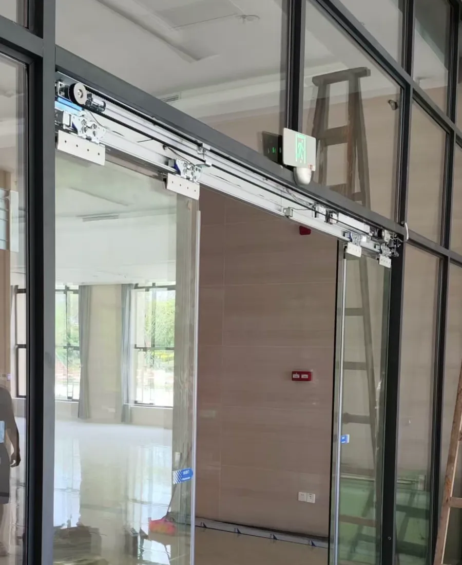
Automatic door operator and rail components, showing the area where power and control connections need coordinated access.
1. Start with the door system, not a generic electrical point
The selected operator is the starting point for power planning. Its installation information determines the required supply arrangement, connection position and the space needed for safe access. The operator choice itself should take account of door-leaf weight, opening size, frequency of use, surroundings, noise expectations and ongoing parts support. A small internal office entrance and a busy shopfront may therefore need different coordination even if they look similar from outside.
Before electrical work is finalised, provide the door layout and confirm where the operator will sit. A concealed operator within a fascia, a surface-mounted unit and a system associated with a glass entrance each present different access and routing constraints. A useful safe check is to look along the proposed head track and identify obstacles such as air-conditioning trunking, signage fixings, sprinklers, ceiling framing or existing conduits. Do not drill or open a finished bulkhead simply to trace a suspected route; concealed services need proper checking.
- Provide the intended door type and opening arrangement.
- Record the clear opening, door-leaf construction and nearby fascia or ceiling space.
- Identify any access-control, intercom, push button or building-system connection early.
2. Bring a suitable supply to an accessible operator area
Plan a dedicated, properly coordinated supply route to the operator area rather than treating power as an afterthought. The connection should remain accessible enough for inspection, isolation and maintenance without dismantling unrelated shopfront finishes or ceiling work. Where the operator is hidden above a ceiling or behind a fascia, agree how a technician will reach it after handover. A neat appearance is valuable, but a fully sealed access route can turn a minor fault check into disruptive work.
At an existing entrance, photograph the whole doorway, the upper door area, the closest visible electrical points and the route back towards the distribution area where practical. These photographs do not prove what is inside a wall or ceiling, but they help identify likely constraints before a site visit. If a door is already behaving inconsistently, include the operator label, any indicator lights and a short video with sound. A clicking relay, repeated attempt to move or complete loss of response can all be relevant observations, but they are not a safe basis for opening electrical covers yourself.
- Keep the operator connection area reachable for future inspection.
- Avoid relying on loose extension leads as a permanent arrangement.
- Coordinate an isolating arrangement and connection method with the selected equipment and site electrical design.
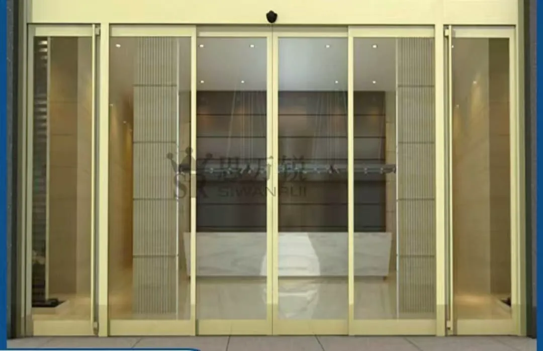
Framed glass shopfront entrance, illustrating how door framing, fascia and nearby finishes affect cable routes.
3. Plan cable routes around moving parts and finishes
Automatic doors may need more than one cable route. The main supply serves the operator, while controls and signal devices may require separate low-voltage connections. These can include activation sensors, door-zone safety sensors, access-control readers, release buttons, key switches, intercoms or monitored interfaces. Their final route depends on the construction of the entrance, not only on the shortest line between two points. Keep this coordination visible on the site layout so one trade does not cover another trade’s required path.
The moving zone needs particular care. Cables should not hang into the rail, rub against a door hanger or pass where a removable cover will pinch them. Look for signs of a poor existing route: loose cable ties, insulation marks, covers that will not sit flat, a door that catches only after a panel has been refitted, or intermittent operation when the door moves. These observations are useful to report. Do not pull on loose wiring or try to secure it close to live connections; arrange an inspection where there is damaged insulation, burning smell, heat, moisture or repeated electrical tripping.
- Map routes before closing ceilings, wall linings and fascia panels.
- Keep low-voltage control wiring organised and identifiable.
- Avoid routes where a moving leaf, hanger, rail or cover can trap or damage a cable.
4. Treat sensors and access control as separate functions
A person approaching the entrance and a person standing in the doorway create different risks. An activation sensor tells the door to open when someone approaches. A door-zone safety sensor helps the system respond to people or objects in the closing area. One device must not be assumed to cover the role of the other. During planning, note where people queue, turn from a corridor, push trolleys, use wheelchairs or pass close to the glass; these patterns affect suitable device positions and later adjustment.
Access control adds another decision layer. A card reader, keypad, intercom, exit button or reception release may need cables, mounting positions and a clear operating logic. Decide whether authorised users can enter from one or both sides, whether staff need a different route, and what the door should do outside normal opening periods. If a device is being fitted on or near glass, confirm the glass type, size, weight, openings, hardware and environment together. Thickness alone does not establish whether an alteration is appropriate.
- List every device that should open, hold or restrict the door.
- Distinguish activation sensors from door-zone safety sensors.
- Agree reader, button and intercom positions before glass, cladding or joinery is completed.
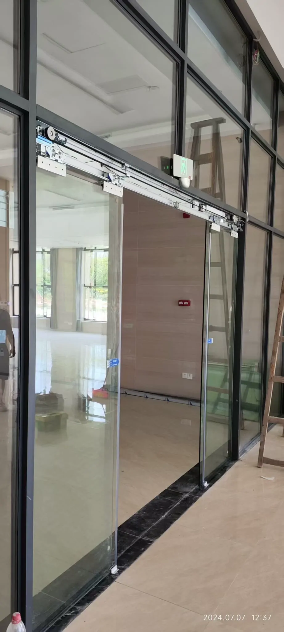
Glass automatic door system components, with the operator area kept accessible for inspection and maintenance.
5. Confirm interruption, safety and building interfaces early
The question is not simply whether the door has power; it is how the entrance should behave when normal power is unavailable. Depending on the system and site design, this may involve a backup supply, a release arrangement, access-control behaviour or a different means of passage. Discuss the intended user journey with the property manager, tenant or building team before cabling is concealed. The door’s required logic must be compatible with the selected equipment and the actual entrance, so it should be recorded rather than passed verbally between trades.
Where fire signalling, escape routes, accessibility or structural safety may be relevant, treat them as design issues requiring confirmation for the specific site. Do not assume that an existing nearby door proves the correct arrangement for a new one. A useful preparatory step is to collect drawings or photographs showing the entrance in relation to corridors, reception desks, gates and other doors, then identify the parties responsible for the building controls. This helps avoid last-minute changes after the operator, glass and finishes have already been installed.
- Decide the intended behaviour during a power interruption.
- Identify any required connection to fire or building controls at the design stage.
- Keep emergency escape and accessibility decisions subject to site and relevant professional requirements.
6. Prepare useful information for a site check
For a new installation, photographs are most useful when they show context rather than only a close-up of the doorway. Stand far enough back to include the opening, adjacent walls, ceiling line, nearby electrical points and any reception counter, shutter or access device. Then take close views of the upper frame, proposed operator position and areas where cables could enter. Add a simple sketch showing the direction of travel and which side is public, staff-only or controlled. This gives the installation team a clearer basis for planning a site visit.
For repair or alteration work, describe what the door does in order: for example, whether it detects a person, starts to open, stops part way, closes unexpectedly or remains open. Record whether the problem occurs every time, only at certain times, or after rain, cleaning or nearby work. Keep people clear of a door that moves unpredictably, and do not bypass sensors, force the leaves or alter control wiring. A remote review can help decide what to inspect, but an on-site assessment is needed before confirming the cause or changing safety-related settings.
- Take one full-width entrance photograph from each side.
- Photograph the head area, ceiling or fascia, nearby controls and visible cable routes.
- Include equipment labels, indicator lights and a short video with sound if diagnosing an existing door.
Common questions
Can the power point be placed anywhere near the doorway?
The location depends on the selected operator and the entrance construction. It is usually better to plan a protected, serviceable route to the operator area than to leave a visible extension lead or an inaccessible connection above a finished ceiling. The installer should confirm the final arrangement after checking the door system and site conditions.
Can an existing glass door be converted without reopening finishes?
It may be possible, but this needs an inspection of the existing door leaves, supporting structure, rail space, frame and glass hardware. A cable route that looks simple from the room side may interfere with the door movement or require unsuitable alterations to the glass or frame.
Are photos enough to diagnose a power or wiring problem remotely?
Photos can support an initial discussion but cannot confirm the final routing or connection method. Send a full entrance view, the operator label if fitted, nearby ceiling and wall areas, any control devices, and a short video showing the symptom. An on-site check is still needed where safety functions, concealed services or structural support are involved.
Send photos on WhatsApp
If you are planning or investigating an entrance, send WhatsApp photos of the doorway, nearby power points or distribution area, ceiling or fascia space, and any existing labels. A short opening-and-closing video with sound is also useful.